Construction of a Sinking (Dishing) Hammer
By Scott Martin
Yes, this needs to be updated, but for now a “mostly there” conversion of the original article so that you don’t have to go hunting through a million different sounces to find how to build the dang hammer… Last updated March 11/2013
Introduction
One of the most useful sets of tools for an armourer to have is a wide assortment of hammers, from simple ball-peins and sledges to hammers that support more advanced techniques such as raising, sinking, embossing, planishing and surface texturing. While many of the techniques used by armourers are very similar in form to those used by contemporary jewelers, the scale at which armourers work (thicker and stronger stock, and much larger forms) tends to limit the number of jewelers tools that can be purchased which are appropriate for armouring use. This fact, coupled with the almost prohibitive costs associated with jewelers tools and the fact that most armourers have a wide range of tools appropriate to making tools results in most armourers converting or building tools to suit their needs. While this article deals specifically with how to convert a readily available hammer (generally either a mini-sledge or large ball-pein) into a sinking hammer, the techniques discussed are appropriate for converting a wide range of tools.
For those intrested in more authentic medieval construction techniques for hammers, the book “The Complete Modern Blacksmith” by Alexander Weygers has been suggested by Thomas Powers, a blacksmith friend. (Ten Speed Press, Berkeley, CA, 1997
ISBN: 0898158966)
Materials:
The materials required can vary a great deal, so I will try to establish some rough guidelines instead of giving a detailed list of the tools that you must use, I will detail a list of the tool uses, along with a few suggestions as to what will work, and allow personal preference (and tool availability) dictate the rest. In the most general terms, you will need a hammer to convert, a coarse abrasive for rapid stock removal and a fine abrasive for blending. Optional, but Highly recommended are abrasives sufficient to get the surface of the hammer to a 400-600 grit finish, and polishing equipment to bring the final hammer face to a high polish.
| Purpose | Suggested Tools |
|---|---|
| Safety Equipment | Eye protection: goggles, glasses or a Lexan Face shield |
| Hearing Protection: hard earmuffs or “popcorn” foam inserts | |
| Gloves: something thick enough to protect both from abrasives and from the heat of prolonged working, especially if you are finishing with polish | |
| Breathing equipment: A HEPA rated respirator is recommended, at the very least use a disposable dust mask | |
| A Hammer to Convert |
8 Oz Ball Pein: This will make an excellent riveting or edge-rolling hammer |
| 16-24 oz Ball Pein: This size hammer will make a good finishing hammer | |
| 2-4 lb ball Pein/Mini-Sledge: The 2-4 pound range of hammers make excellent heavy working hammers for armour. I find that 2-3 Lb is good for general use, and 4 Lb is excellent for working on heavier materials such as those used in helmets | |
| Measuring/Marking | Marking tools: “Sharpie” type permanent markers |
| Measuring tools: Metal Ruler, tape measure etc. | |
| Radius measuring tools: dividers or a compass | |
| Rigid Patterning Material: Cardstock, quilters patterning plastic etc. | |
| Coarse Stock Removal | Angle Grinder with stock wheel (24 grit) |
| Bench Grinder with coarse wheel | |
| Belt Sander (80 or lower grit) | |
| A Metal Lathe | |
| Fine Stock Removal/
Coarse Blending |
Angle Grinder with “blender” wheel or sanding disks (120 grit) |
| Bench Grinder with fine wheel | |
| Belt Sander (120 or higher grit) | |
| A Metal Lathe | |
| Fine Blending | Angle grinder with autobody sanding attachment (Velcro sanding pad) and 180, 240, 320 and 400 grit pads |
| variable speed Autobody sander with same pads as above | |
| palm or circular sander with same grits as above | |
| You Guessed it… A Metal Lathe | |
| lots of sandpaper and time… | |
| Polishing | Fine Muslin buff mounted on an angle grinder with Grey, White or Green Tripoli |
| Fine Muslin Buff mounted on a bench grinder or arbour motor, charged with one of the above polishing compounds |
Procedure:
Some thoughts on Safety: When you are removing metal with power tools, a lot of dust, noise, fast-moving particulates (sparks) and heat are generated. Wear appropriate safety gear (Especially eye, ear and hand protection) and be aware that while you are removing metal (probably iron or steel) the material that your grinding stones are composed of are also being degraded and turned into dust. These particulates are generally silicates, and a lot worse for you than most dust, so a respirator is a very good idea.
You will need to start with an idea of what the purpose of your hammer will be: Is this a nice light riveting hammer, or a crushing brute designed to mash helm tops into submission? Do you need a sharply curved face to form deep 14th century elbow couters, or a more gradual surface for helms or spaulders? Once you have decided on the purpose for the specific hammer you want to build, then you can determine what weight and curvature this hammer should have. In general I recommend that the first hammer be around the 2 Lb (32 Oz, or ~900 g) with a fairly gentle curve (6-10″ diameter). Note that it is easier to remove the excess material if you do not have to worry about the handle getting in the way, so I often remove the handle before starting work on the hammer face.
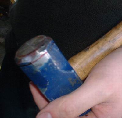
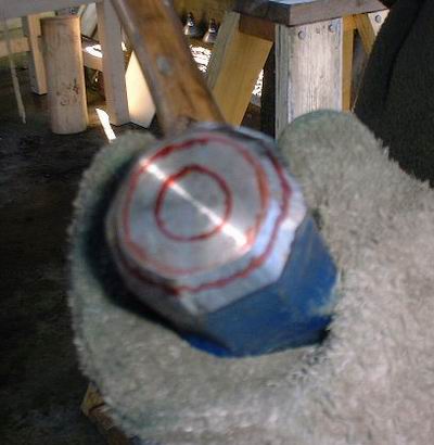
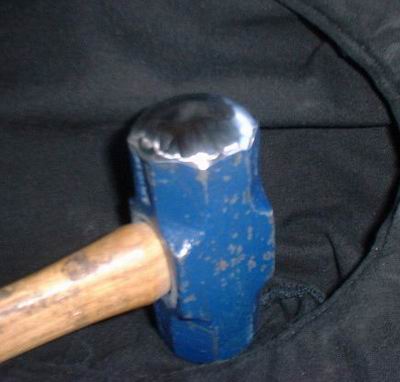
Once you have determined the size and curvature of your hammer, figure out how much metal must be removed from the edge of the hammer: there are a number of formulae that I could provide, but the easiest thing to do is to draw a circle of the appropriate radius on cardstock or light cardboard, and cut out the concave part (throw out the circle and keep the part that was outside it) you can then fit the circle to the top of the hammer and the space between the hammer face and the middle of the curve is the amount that needs to be removed from the sides. Figure 1 is the hammer face, figure 2 is the hammer face with the circle gauge placed over it.
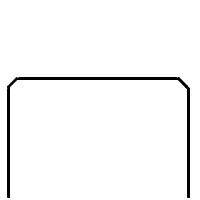 |
 |
| Figure 1 | Figure 2 |
|---|
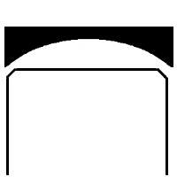
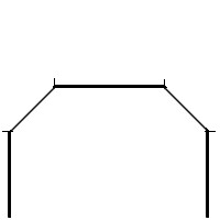
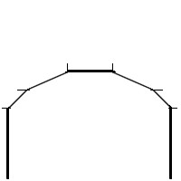
Once you have determined how much material must be removed, mark this as a line around the hammer at the depth desired. this will be a line around the outside of the hammer. In addition, mark this same distance in from the edge on the face of the hammer: this will be a circle on the face. Figure 3 is a schematic (top or side view) diagram of the hammer: the tick marks on the outside show where these marks need to be placed, while the shaded areas show the metal that will be removed. Figure 4 shows these lines drawn onto an actual hammer. Note that almost all hammers have a slight (generally 45°) edge bevel, so this is included in the diagrams.
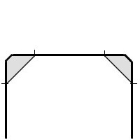 |
 |
| Figure 3 | Figure 4 |
|---|
You will now need to remove the metal between these two (parallel) lines, and they should form a 45″ angle to both the face and side of the hammer head. I find that it is generally easiest to line the bevel up with my grinder edge, and continue this angle as I remove the metal. While I could continue at great length with the “correct” way to remove metal in this process, it is probably better if I mention some generalities to keep in mind, and if your hammer looks like figure 6 when you are finished, you did it correctly.
Useful things to keep in mind:
- Let the machine do the work: if you use a lot of pressure you will probably only increase the amount of time you will spend cleaning up the rough spots later
- The angle is very important: if you can keep a consistent 45° angle, most of your work will be done for you
- keep the hammer moving: if you stop, grinders (and to a lesser extent sanders) will tend to “bite” into the metal, making it more difficult to move smoothly and evenly
- Good work takes time: trying to save 5 minutes will often cost you 30!
- Do not work at all near the center of the hammer face: any metal removed here (even by accident) will result in having to remove that amount of metal from the entire hammer face, so this is an area where it pays to concentrate.
For this stage, I generally use an angle grinder clamped into a vice: it is a very coarse method of metal removal, but it is significantly faster than using my (under-powered) bench grinder. the fact that the wheel is parallel to the ground gives me a better visual “cue” for my 45° angle on this stage. Once you have finished this stage, you should end with a hammer face that resembles Figures 5 and 6, below:
 |
 |
| Figure 5 | Figure 6 |
|---|
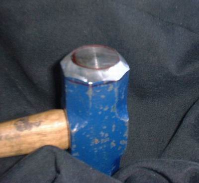
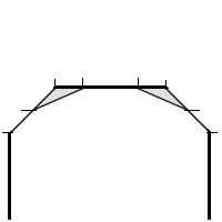
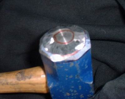
We now need to do one more “bulk removal” pass to rough in the hammer face: this is done in a very similar manner to the previous one. The first line that we will draw is in the middle of our 45° slope, the second line (circle) is halfway between the center point of the hammer face, and the edge of the new (larger) bevel on our hammer face. Figures 7 and 8 show these markings, and as before the shaded area (in figure 7) will be removed. Note that in figure 8 the line delimiting the inner limit of our 45° bevel line is still visible: the new line on the face is the circle towards the middle, which is basically a circle of 1/2 the radius of our original “bevel” line. If you looked at a side view of this hammer, you would still see residuals where the side “bevel” line was marked.
 |
 |
| Figure 7 | Figure 8 |
|---|
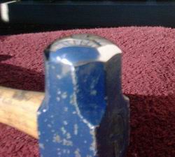
The resulting face now looks almost like a rounded sinking hammer: the “steps” are now gradual enough that we no longer need to use coarse metal removal tools. Once your hammer looks like the one in figures 9 and 10, you are ready to change to a less aggressive metal removal medium and blend the face into a smooth surface.
 |
 |
| Figure 9 | Figure 10 |
|---|
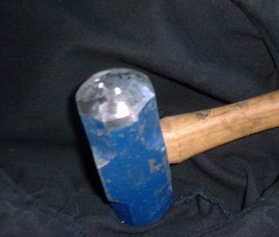
At the “blending” stage, what you are trying to accomplish is the “softening” of the sharp transitions that have been left where the angles of metal removal have changed suddenly. While it is possible to use a hammer such as that displayed in figure 11 to work on metal directly, it is generally better if you can at least “touch up” the finish by using an abrasive of about 180 grit on it, as shown in figure 12. Once you have the “blended” even curve (which you can test by placing your curve gauge on it) it is a simple matter to rock the hammer back and forth across your abrasive tool, such that each time you change to a finer grit you are moving the grit at 90° to the previous line of scratches. this will have the effect of removing all of the “high” spots, and bringing the entire hammer down to a consistent curve.
 |
 |
| Figure 11 | Figure 12 |
|---|
By this time the hammer head is probably getting quite warm: this is not an issue as long as the head does not heat to the point that it is uncomfortable to hold (you are wearing gloves right?) since we are not terribly concerned with the temper of the hammer (Most hammers available these days do not have tool steel heads, so there is no hardening to worry about removing) We can continue to use progressively finer grits until we get to 400 to 600 grit (as seen in Figure 13) at which point you will start to see yourself reflected (poorly) in the surface of the hammer face.
At this point, I would strongly recommend polishing the surface of the hammer, since this will allow you to find surface imperfections on the order of 1/1000″, which you will not be able to see in any other way. Be aware that Polishing will heat your hammer face faster than anything that we have done to date, so you may want to take an hour or longer break to allow the hammer to cool before starting.
After changing to a polishing wheel and polishing compound, you will quickly (within 5-10 minutes) be able to get the surface from a 400 grit finish to a mirror. The easiest way to polish hammer faces is to rock the hammer face up and down, and then side to side. This can be a good technique to use on armour, but remember that most armour is much more prone to thinning than a hammer (~1/16″ thickness instead of 3-4″ of thickness) so care must be used. Once you have mirror finished your hammer, any defects will be readily visible as image warping when you look at the face. Any time you see a significant distortion there is probably an irregular area in the surface of the metal. If this irregularity is minor, then it is probably best to ignore it, since hammering it into metal will slowly push the face into an even curve, and regular polishing will tend to remove the “high” points faster than the low ones. If there are any deep scratches remaining then one of the intermediate sanding steps was incomplete: go back to your last grit and then re-polish. if this does not work, then go back and repeat the last two sanding stages, and so on. If you have major imperfections in the face of your hammer you can follow exactly the same course of action (go back 1 or more sanding stages, then re-polish)
 |
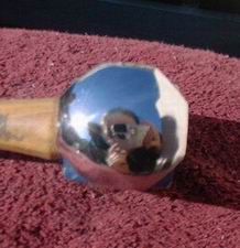 |
| Figure 13 | Figure 14 |
|---|
Acknowledgements:
I would like to offer my thanks to a number of folks:
- To Jeff de Boer, Rob Valentine and Ilkka Salokannel who made the pursuit of the art seem like enough fun to get me to apply myself and have fun at it. (and took the #@&$ ball pein hammer away from me long enough to show me what a useful armouring hammer looked like)
- Thanks also go to Eric Slyter for his photos (that’s his reflection in figure 14) and nagging me long enough to put down my hammer and actually compose this article.
- Hammer Gauge suggestion provided by Ron McWilliams (Credit where credit is due)
- And of course, thanks to all of my friends who have put up with my banging on metal all these years!
All rights reserved.
Nice Work