Introduction:
Medieval armour used a number of closure and lock mechanisms that are no longer in common use. In the middle ages, many of these closures and mechanisms, as well as catches, buckles and hinges, were made by locksmiths instead of armourers. Unfortunately, since there is no longer a demand for these specific types of items, not only do we need to research how to use these components, we often need to actually manufacture them.
The purpose of this article is to demonstrate the reconstruction of a spring lock closure which was commonly used on helmets starting in the mid 15th century (generally on visored sallets and armets) and continued in use until armour was no longer used for anything other than ceremonial purposes. There are a couple of notable exceptions that should be noted in this article: I did not grind the outer rivet heads flush with the surface of the helmet since the rivets are hidden by the lobster tail, and I did not include a sneck hook to secure the pin, since I have found that a separate cotter pin tends to survive better in the western martial arts tournament environment. A follow up may include how to build and attach a proper sneck hook.
Technical Overview
So how does a spring pin closure system work? This system works on helmet visors in the same way that a sliding bolt works to hold a door closed: when the pin is extended (passing through the helmet and the visor) then the visor cannot move without tearing through the pin. When the pin is retracted then the visor is free to pivot. A couple of diagrams of the mechanism and how it operates are shown below:
 |
 |
 |
 |
| Engaged Spring Pin | Disengaged Spring Pin |
Notice that the release button and the locking pin both pass through the helmet, but only the locking pin passes through both the visor and the helmet. The release button is needed to push the locking pin entirely through the visor – if you did not have this to “lever” the locking pin through the visor you would only be able to push the locking pin flush with the surface of the visor – and it would still be locked.
Procedure:
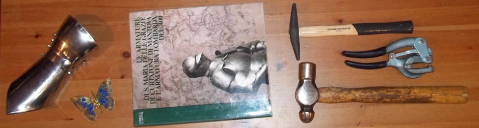
You should start by making sure that you have all of the tools and materials available and ready to use – it’s frustrating to have to stop a project to spend an hour or two shopping for a bolt that you were sure was in your toolbox
Materials:
- A visored helm
- A piece of spring steel – I find that a 0.070″ spark plug feeler gauge is ideal, others have used pieces of hacksaw blade, steel strapping or spring steel sheet / strip (410 stainless)
- brass or steel round stock 1/4″ to 5/16″ diameter by 1/2″ – 3/4″ long for the locking pin
- a 3/16″ rivet or an additional piece of round stock for the release button
Rivet(s) for the spring pin - (Optional) Stock for a sneck hook (optional) use stainless or spring steel: if you are forming from sheet, then from 16 Ga (1/16″ / 0.0625″ / ~1.5 mm) to 12 Ga (1/10″ / 0.10″ / 2.5mm) thickness
Tools:
- A roper whitney hand punch (trying to drill tool steel with a spring temper can be an exercise in frustration)
- A drill press
- A good file, preferably one with a “safe” edge
- A hand drill
- A Foredom or Dremel flex-shaft tool (if available)
- A vice or machinists vice to hold the round stock while drilling
- Various sizes of drill bit. At a minimum one each for:
- Drilling pilot holes (1/16″ – 3/32″)
- drilling out the holes for the studs (1/16″ – 1/8″ larger than the stud material or rivet used for the release button)
- Drilling the holes for the rivet(s) in the helm (the exact size of the helm rivets – I used 4x 1/16″, extant medieval helmets generally use a single 1/8″ – 3/16″ rivet)
the hole drilled through the locking stud (3/32″ – 1/8″ for a cotter pin, up to 5/32″ for a sneck hook)
Preparation:
Before starting it is important to make sure that the helmet is appropriate for securing with a spring pin. You will need to make sure that the visor overlaps the helm body by at more than 3/4″, since you will need to punch a hole through the helm and the visor leaving enough room on both that the spring pin will not tear through – 1/4″ is about the minimum for this, since the hole for the pin is slightly over 1/4″, and the “leading” and “trailing” edges each need 1/4″. You will also need to ensure that the visor tightly fits the helm at the point where the spring pin will pass through – there should be no more than about a 1/16″ gap between the two plates.
Layout.
There are two ways that you can lay out your spring pin closure: you can start with the piece of spring steel and transfer the appropriate measurements onto the helmet (my preferred method) or you can start with the helmet and transfer the measurements onto the spring steel. The reason that I prefer to start with the spring steel is is means that I don’t need to worry about lining up the holes in the helmet – the spring steel will fit where it needs to, and the holes in the helmet will be in line and in the correct place. This also means that the spring steel (which must be punched) gets used as a template onto the steel of the helm (which is generally drilled). Note that spring pins are a “consumable” and eventually you will replace them, so you will get practice laying out the spring pins based on the helmet (unless you were clever and made a copy of the “master” spring steel plate when you made the original…)
Regardless of which way you do the layout, the cardinal point for the spring pin will be where the pin passes through the visor and the helm. I use a clamp to hold the visor in the position that I want it to lock (if this is a sallet this is your last chance to make sure that your eye slot is open the correct amount!) and then drill a pilot hole (1/16″ through both layers of material. If I am satisfied with this placement I will then ream it out with a 3/16″ hole (since that is the size that I use for my pin hole in the spring steel) but is small enough that if I am in the wrong location I can move it and try again – if it’s less than 1/16″ off you are out of luck, but my helm tolerances are never less than 1/16″… Bolt the visor to the helmet through this hole and use a marker to draw on the edge of the helmet at the edge of the visor – the release button must be AT LEAST this far from the locking pin or this will not function properly (or you will need to trim your visor). I generally place the release button about 1 1/2″ from the locking pin. Note that for this example the critical placement was to ensure that the rivets holding the spring pin were hidden by the lobster tail – as a result I marked the visor in its closed position and then held the spring pin to the helmet ensuring that the spring pin hole was at least 1/2″ overlapped with the visor, and that the hole for the release button was between the visor and the lobster tail.
I will assume that you are using the spring steel for layout: if you want to do layout on the helmet instead then reverse these instructions (punch holes in the helm and transfer locations to the spring steel) but be aware that if you are using the helm for layout, then mark where you want to place your release button and draw a straight line between the two holes, and extend it about the same distance toward the back of the helmet – these 3 points MUST be in a straight line for the spring pin to function properly.
If you are using the spring pin for layout then you will need to punch the holes for the spring pin, release button and attachment rivet(s) now. I like to use feeler gauges for the spring steel. Lee Valley used to sell a set that was 3-4″ long, and up to 1.2mm thick, now their thickest ones are about 0.5mm and inappropriate. Punch holes for the locking pin at one end, the release button (in the middle) and the attachment rivet (at the other end). these should all be roughly 3/16″ so that you can put a “shoulder” on your pins (or in the case of the release button, fit a 3/16″ rivet directly into it).
Once the holes are made in the spring steel bolt this through the helmet (on the outside) and line it up where you think a good position would be for the release pin.
Making the components:
The first piece that I make (after the helmet) is the piece of spring steel that all of the other pieces will be connected to.  This is simply a piece of spring steel with a spring temper between 0.5-1.6mm (0.025″ to 0.625″ / 24 ga – 16 Ga) thick with holes punched for the spring pin, release button and attachment rivet(s) – in my example I used 4 small (1/16″) rivets, period examples used a single larger (~3/16″) rivet, and in practice this is easier to work with. You should use a roper whitney hole punch to make the holes, because trying to drill tempered spring steel is incredibly difficult – if you don’t have a hole punch then using titanium bits in a drill press is strongly recommended – high speed steel bits are unlikely to be hard enough to cut the material.
Both the locking pin and the release button are made from pieces of round bar stock which are shaped in a drill press or lathe. these two pieces are identical except that the spring pin has a hole drilled through so that it can be engaged by a cotter pin or sneck hook. To start the spring pin, center punch and drill a small (1/16″) pilot hole in the spring pin roughly 2/3 – 3/4 of a diameter from the end of the rod (so if you are using 3/8 stock the hole will be a bit over 1/4″ from the end
 |
 |
| Center punch | Drill pilot hole |
Then the hole can be reamed out to an appropriate size – be careful drilling out a hole larger than 1/2 the diameter of the stock: a 1/8″ hole is about as large as you want to go for a 1/4″ pin – you can do a 3/16″ hole on 5/16″ stock, but 3/8″ stock is safer for this size hole. Once you have drilled this hole, cut the shaft off at about 3/4″ (this will give LOTS of excess material) and insert it into the chuck of your drill press. Turn on the drill press and use a file to round the end of this piece
 |
 |
| reaming out the hole | Rounding the head of the spring pin |
The button is done the same way, but without drilling a hole in the head. Once you have the spring pin head rounded, determine how long the spring pin needs to be for the hole to be just above the level of the visor. I block the “inside” of the hole through the helm with a sheet of steel and then put a piece of brass through the visor and helm until it bottoms out. Draw a line on this piece of brass with a sharpie and this is the “bottom” of the hole. I then add 1/8″ to that length and mark that length from the bottom of the hole drilled in the spring pin, this is where I will cut (with a hacksaw or jewelers saw) the pin. Once I have cut the pin I will put it in the drill press with 3/16″ of material protruding past the bottom and use a file to remove the material until I have a nice “shoulder” and the shank of the pin will pass through the hole that I have punched in the tab of spring steel material.
 |
 |
| Spring pin cut to length | Bottom filed to fit the spring strip |
Before I race to attach this, it’s time to make sure that all of the pieces will work properly with the helmet. As noted above, the easiest way to fit this properly is to start with the hole for the spring pin and build the closure “back” from that. For this helmet (both because I wanted to not re polish the helm and I had decided to use 4 small rivets instead of one big one) I built it from the rivet attachment forward. Both work, particularly if you have a lot of overlap on the helm from the visor – I had about 1.5″ (40mm) so I wasn’t particularly concerned with alignment, and the helm was designed to have a visor opening of 3/4″ for SCA combat, so making an error of up to 1/4″ would allow the helm to be legal for combat.
Since I’m starting with the rivet attachments, I closed the helm to it’s proper “closed” position and drew the edge of the visor onto the helm skirt – this allowed me to make sure that the spring pin hole would be well inside the visor area to engage, and that the release button would be outside (this is the curved black line drawn on the helm). Holding the attachment strip I fiddled it until I had the alignment I wanted – good overlap on the visor for the spring pin, clear of the visor and the lobster tail for the release button, and all of the attachment rivets in a position where the lobster tail would cover them.
 |
 |
| Marking the rivet holes | holes marked |
The holes marked were then drilled using a foredom (flex-shaft) since this is a much easier way of drilling holes through thick material than a hand drill. Two holes were drilled (opposite corners) then the strip was bolted into place and the remaining holes were center punched and drilled
 |
 |
| bolted through 2 holes | Drilling remaining holes |
With the spring plate fixed at one end, it was easy to press the plate into place and mark the other holes (spring pin and release button) which were marked and pilot holes drilled. The visor was then attached and aligned, and the spring pin hole was marked and drilled on the visor. All holes were then drilled out to their full size (5/16″ since I was using 1/4″ stock for the spring pin and release button)
 |
 |
| Lining up the remaining holes | All holes drilled |
Now it’s time to put all of the pieces of the spring pin together, the spring pin, the release button and the attachment rivets. this is the last chance to make sure that the pieces fit together properly, so a final “dry fit” of the spring pin and release button is done before assembly
 |
 All the pieces Dry fitting All the pieces Dry fitting |
The smaller diameter section that we cut into the spring pin and release button earlier is passed through the piece of spring steel and then peaned over, much like a rivet. You can’t do this safely with the spring pin, since the hole will make it easy to crush with over-vigorous hammering, so pass the drill used to make the hole through the hole, and use this to align the spring pin while you pean over the end. Note that you generally want the hole to be vertically aligned, so that a sneck hook or cotter pin can sit vertically in the hole.
 |
 |
| Spring pin put into place | Spring pin ready to rivet |
Once the spring pin and release button are securely riveted onto the backing strip, test the fit by bolting the assembly to the helmet – it’s normal for the pin to bind somewhat as it is release (the release button is pressed) because the arc described by the backing strip pushes the pins out of alignment. This is easily solved with the judicious application of a round file. DON’T file the visor hole, the visor can rotate slightly to clear this arc, and enlarging this hole will put more strain on the spring pin if the visor is struck in use.
Once you are satisfied with the fit you can rivet the spring pin assembly to the helmet. Before you do this, you will want to countersink the rivet holes on the outside of the helm – it will both increase the amount of “hold” that the rivets can exert, and if you can’t hide the rivet holes behind a lobster tail you will need to grind the rivet flush on the outside of the helmet, which was commonly done on sallets, armets, close helms and burgonets. Countersinking is most readily accomplished using a larger drill bit, and drilling 2/3 of the way through the thickness of the helm is my rule of thumb for a good amount of grip without weakening the rivet location.
 |
 |
| Countersunk rivet holes | countersink profile |
Now that the spring pin is attached, the rest of the helmet can be assembled
 |
 |
| Engaged spring pin locking visor | The completed helm |
While the profile of this helmet is very “re-enactor” the spring pin functions the same way a more “correct” reproduction would. If mounting a sneck hook this would be most commonly be mounted either on the visor in front of the hole for the spring pin, although it could be mounted on the helm above the release button and engage at a slight angle.
Copyright 2013 by Scott Martin
Jolly well done.
Very good instructional piece! Easy to follow, and explains every detail needed, even for a beginner. Excellent work!
Love the photos! Thanks for the step by step instructions. You have prettier tools than I do 😉